Notes on Floppy Disks
Floppy disks are a thing of the past. Except if you’re in retrocomputing like I am. Recently I had to repair an old, vintage Commodore Floppy Disk drive due to leaking electrolytic capacitors. It was a dual drive and when re-assembling it I found that one of the drives had one head with a high error rate. But when I tried to read up on floppy drive theory and operation, I found it unbelievably hard to find anything useful on the web. So here are my notes of what I found.
[Edit 1: 2019-01-04: Added a table with more details on the various encoding formats]
[Edit 2: 2019-01-05: Apple 6-and-2 added]
Basics of magnetic media operation
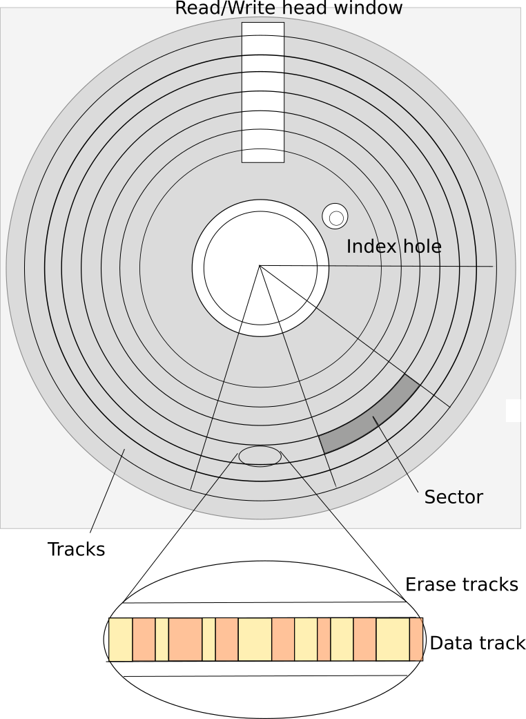
Floppy disks store their information in magnetic material coated onto a plastic disk surface. This disk is rather flexible, that is where the name comes from. If you don’t remember round disks, that is because they were protected by a square plastic enclosure that only leaves a ring in the middle - so the disk can be turned - and an opening for the read/write head to actually access the spinning disk.
The properties of the magnetic medium vary depending on the material used. In [density] you can see that standard floppy disks use a variety of different materials, from iron oxide to Cobalt and Barium ferrite. Disks differ in the amount of magnetic flux needed to write to them (Coercivity, measured in Oersted), thickness of the coating, and, most importantly the bit density, measured in “bit per inch”.
What you can also see is that the floppy disks have evolved. It started with 8 inch disks created by IBM and soon becoming industry standard [history]. This standard had 77 tracks - a number to remember for a later discussion.
The 8 inch drives were expensive, so smaller drives needed to be developed. Alan Shugart’s initial 5¼ inch disk drive, the “SA-400” was widely used in many early microcomputers. It was single sided, and had 35 tracks (only, compared to the later 40 tracks standard).
I fact a variant of the SA-400 was used in the Apple Disk-ii as well as in the early Commodore disk drives, the 2040 and 3040 (and later 4040) drives. Both used the “SA-390”, which actually was a stripped-down version of the SA-400 without the logic board, so Apple and Commodore both built their own logic board for the drives - with some consequences as we will see.
Information is recorded on magnetic media using a read/write head consisting of, usually, three coils that allow erasing (before writing, erase a slightly wider track on the media to avoid interferences) and writing the data either as + or - polarity. Although, from a naive point of view one would probably assume the magnetic field going the media perpendicular to the surface, the first floppy disks used longitudinal recording. As it does not matter for the following discussion I will not go deeper into this, you can look up more details at [perpend]. Just as visual impression look at the visualization of magnetic information in [oper], where tracks are going from bottom to top, and in each track you can see the little slices of magnetization that represent the data.
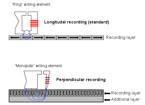
(Public Domain image by from https://commons.wikimedia.org/wiki/File:Perpendicular_Recording_Diagram.svg )
Note that perpendicular recording requires an additional layer for the return flux - that was probably not available in the early floppy disk medias and would potentially have prevent double side use then.
More on magnetic recording can be found in [magnetic] and [magrec].
Writing to the disk is “easy”, it is applying a magnetic field strong enough to magnetize the media on the disk. How is the data read? The same magnetic head is moved over the magnetized media, but without any write current applied. As electromagnetism goes, we do not get a signal on one line for one type of magnetization, and another signal on the other line for the other magnetization - we only get a pulse signal when the magnetization changes! So the real information is coded in the places where the magnetization changes, not in the actual magnetization (Note that the polarity does not matter - the read circuit detects both magnetization changes back and forth as a 1-bit).
Of course there are now two ways to encode data in magnetization changes, if you divide the stream into boxes of fixed time. One would be to encode the magnetization in the data, so any change in the magnetization within a time box would flip the data bit. That, however, is not what was used, instead a 1 in a time box changes the magnetization, and a 0 keeps the same magnetization. This in fact corresponds 1:1 with the read signal - if a change in magnetization is detected, a 1 is read, if not, a zero. Only when writing you now do not have to apply the data to the write coils directly, but flip the magnetization on 1-bits.
A lot of dry stuff, but we’re getting to the fun part soon. Just one thing. The quality of the media is determined (among other properties as given above) by the “bit per inch” density of the data. This determines the number of 1-bits, or magnetization changes a floppy media can hold per inch on a single track. With a little bit of math we can actually validate some numbers:
- The usual bpi for DD (“double density”) and even QD (“Quad density”) disks is about 5900 bpi [density]
- The most inner track of the floppy is at a radius of 1.354in (for 40 track disks, see [herb]). This results in a circumference of 8.5in in the inner track.
- The outer track of the floppy is at a radius of 2.25in [herb], resulting in a track length of about 14.1in.
- Using these track lengths, one sees that a track can hold about 50kbit of data on the innermost track, and 83kbit of data on the outermost track.
- The typical floppy disk runs at 300 rpm, or 5 rotations per second.
- This resulted in a write rate of about 5/sec*50kbit = 250kbit/sec in the innermost track, but allowed 417kbit/sec on the outermost track.
Note that the usual data frequency of MFM (and of FM, if you count the clock bits as well), is 250kbit/sec. The number of “bits per track” on some disk drives like the Commodore 8250LP drive [CBM] state “50,000” bits (or 50kbit) per track.
Interestingly the [Heathkit] specification for a 8” disk drive states the double density bpi as 6536 bpi, 10% over the standard bpi given for 5¼ in floppies of 5900.
Also note that while the original FM and MFM disks did not change the data frequency across the whole disk, they would waste a lot of capacity on the outer tracks. Commodore would use “zoned bit recording”, where they gradually increased the data frequency in four zones across the disk to increase capacity.
Data encoding and Capacity
Now that we know some basics, and have understood that data is encoded in magnetization changes on the media, how is the data written to disk, and what is the difference between FM, MFM, and GCR?
In principle, with a perfect timing (or a separate, synchronized timing source), you could just write out your data onto the media as it is (switching magnetization on every 1-bit in the data). The problem with this approach is that there is no such thing as a perfect timing - disk drive rotation varies, and so does the speed of the bits as they pass under the read/write head. The Commodore 8250LP disk drive [CBM] states a variance of plus or minus 3% on top of the 300rpm rotational speed. Over a 14.1in outer track that is almost 0.42in or 2.5kbit of difference! Even if you assume a sync per sector, this can still amount to 260bit difference for a sector on a 10 sector disk. So in absence of a clock signal that syncs the data stream to the data clock, the data stream on the disk needs to provide a “self-synchronization” feature, to ensure that the data stream stays in sync with the magnetization stream. This is usually done by ensuring that there are at least some 1-bits in a specific time window to allow the re-synchronization of the read circuit.
All of the codes described here are variants of a run-length limited “RLL” scheme [RLL].
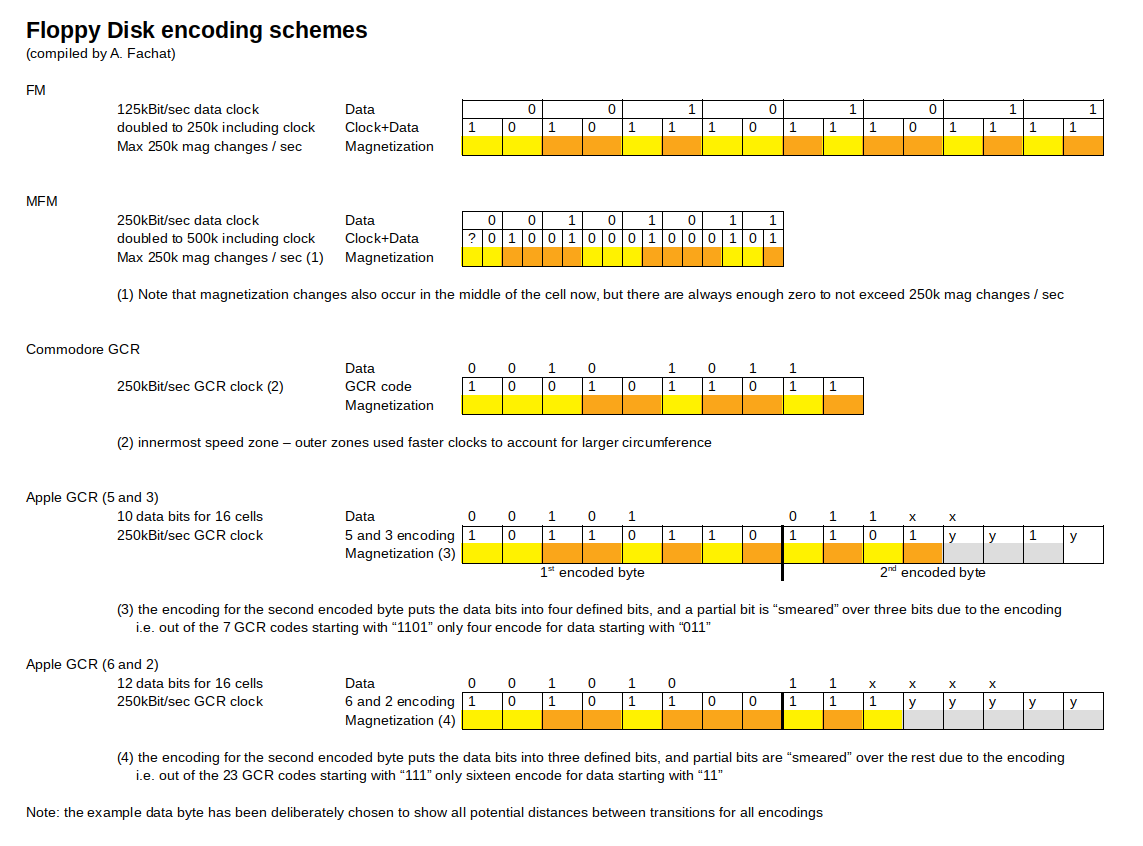
The following diagram shows some common encoding schemes that I will detail below.
[Edit1: table added] In this table I am trying to compare the different encoding schemes in more detail.
| No. | FM | MFM | Commodore GCR | Apple GCR (5-and-3) | Apple GCR (6-and-2) | Comments | |
|---|---|---|---|---|---|---|---|
| Recording Bits | |||||||
| 1 | Recording frequency | 250kHz | 500kHz | 250kHz | 250kHz | 250kHz | Not counting for other (faster) speed zones for Commodore GCR |
| 2 | Encoded bit cell length | 4us | 2us | 4us | 4us | 4us | Length of bit cell on media in time units (inverse frequency [1]) |
| Recording Data Bytes | |||||||
| 3 | Encoded bit cells per data bit | 2 | 2 | 5/4 | 8/5 | 8/6 | According to the respective encoding rules. |
| 4 | Encoded bit cells per data byte | 16 | 16 | 10 | 64/5=12.8 | 64/6=10.67 | [3] times 8 for a byte |
| 5 | Encoded bit cell length for a data byte | 64us | 32us | 40us | 12.8x4us=51.2us | 10.67x4us=42.7us | [4] times the encoded cell length [2] |
| Per Track | |||||||
| 6 | Encoded bit cells per track | 50000 | 100000 | 50000 | 50000 | 50000 | 300rpm means five rotations per second, i.e. 200ms per track, divided by the encoded bit cell length [2] |
| 7 | Data bytes per track (unformatted) | 3125 | 6250 | 5000 | 3906 | 4684 | Again, 200ms divided by data byte length [5] |
| On Disk | |||||||
| 8 | Minimum/Maximum Encoded 0-bits in a row | 0/1 | 1/3 | 0/2 | 0/1 | 0/2 | According to encoding rules, as encoded cells |
| 9 | Minimum/Maximum distance between flux transitions (1-bits) in cell widths | 1/2 | 2/4 | 1/3 | 1/2 | 1/3 | Transitions happen at cell boundaries (see the coloring above), so the length of the 1-bit cell is added to [8] |
| 10 | Minimum/Maximum distance between transitions in time | 4us/8us | 4us/8us | 4us/12us | 4us/8us | 4us/12us | [9] times the encoded bit cell length [2]; all have minimum 4us distance. CBM GCR actually has the largest "gaps" of these |
| 11 | Maximum flux transitions / track | 50000 | 50000 | 50000 | 50000 | 50000 | One track length of 200ms divided by the minimum distance between flux transitions from [10] |
| 12 | Maximum flux transitions / in | 5882 | 5882 | 5882 | 5882 | 5882 | Max flux transitions per track [11] divided by 8.5 inch/track for the innermost track (35 track drive). |
| Advertisement | |||||||
| 13 | Data Bits / track | 25000 | 50000 | 40000 | 31248 | 37472 | Data bytes per track [7] from above times 8 |
| 14 | Data Bits / in | 2941 | 5882 | 4706 | 3676 | 4408 | [13] divided by 8.5in for the innermost track length. Maximum used "bits per inch" |
What can be seen here is that all encodings could use the same media. "Single Density" (SD) media was meant for FM, while "Double Density" (DD) was meant for MFM (or GCR), both with 48 tracks per inch (tpi). Disks for 96tpi or 100tpi were labeled "Quad Density" (QD). It is unclear if they allowed to use a higher rate of flux transitions.
Despite the fact that all media types used the same material (300 Oested, 5900 flux transitions per inch), the "bit per inch" as well as the "Density" ratings have become prevalent, most likely as a form of advertisement for "higher quality", thus more expensive DD or QD media.
FM
Frequency Modulation (FM) is the most simple technique used. It adds a separate clock bit in front of every data bit. This doubles the potential magnetization changes per data byte written (e.g. write of $ff results in 16 magnetization changes). To stay below the limit of 250k magnetization changes per second, the data rate could of course be only 125kbit/sec.
Using this technique it was possible to format disk with 88k of data.
Using FM, one can see that there can be arbitrary numbers of 1 in a sequence, but only a single 0 in a row. FM is an RLL 1/2 (0,1) code.
MFM
In Modified Frequency Modulation (MFM) the number of clock bits used are drastically reduced compared to FM. If you take the two bits, clock and data, as part of a cell, the encoding was as follows:
| Data bit | Encoded cell | |
|---|---|---|
| 1 | 01 | always |
| 0 | 10 | If preceded by a 0 |
| 0 | 00 | If preceded by a 1 |
This means that each data bit was encoded with at most one magnetization change. In addition, there always was at least a single 0 between two magnetization changes. This allowed doubling the recording frequency, as magnetization changes were still far enough apart, as can be seen in the above diagram. One caveat was, and that required the actual double write frequency, that a magnetization change can now be located in the middle of a cell.
The space needed to encode a byte of data was thus halved compared to FM, the disk capacity was thus doubled to 180k.
MFM is an RLL 1/2 (1,3) code. It is “as bad as” FM in terms of overhead bits, but as there is at least one 0-bit between two 1-bits, it can be recorded at double the frequency.
GCR (Commodore)
Commodore used a different format to record data on the disk, Group coded recording (GCR) [CBMGCR]. Here a nibble of data (4 bit) was encoded into 5 bits that had to be written to the media. The conditions for the transformation was that there are
- Not more than two 0-bits in a row
- Not more than eight 1-bits in a row
This resulted in this encoding scheme:
| 4-bit value | GCR code | ||
|---|---|---|---|
| hex | bin | bin | hex |
| 0x0 | 0000 | 01010 | 0x0A |
| 0x1 | 0001 | 01011 | 0x0B |
| 0x2 | 0010 | 10010 | 0x12 |
| 0x3 | 0011 | 10011 | 0x13 |
| 0x4 | 0100 | 01110 | 0x0E |
| 0x5 | 0101 | 01111 | 0x0F |
| 0x6 | 0110 | 10110 | 0x16 |
| 0x7 | 0111 | 10111 | 0x17 |
| 0x8 | 1000 | 01001 | 0x09 |
| 0x9 | 1001 | 11001 | 0x19 |
| 0xA | 1010 | 11010 | 0x1A |
| 0xB | 1011 | 11011 | 0x1B |
| 0xC | 1100 | 01101 | 0x0D |
| 0xD | 1101 | 11101 | 0x1E |
| 0xE | 1110 | 11110 | 0x1F |
| 0xF | 1111 | 10101 | 0x15 |
Using this scheme, Commodore was able to use (at least) ten 1-bits in a row as a sync marker (more on this below).
This GCR code is in fact not as efficient as MFM space-wise, as it occupies 10 instead of 8 cells (at the 250k frequency). MFM however, is more demanding as you need to synchronize your clock at double the frequency (with magnetization changes in the middle of a cell).
Commodore GCR is an RLL ⅘ (0,2) code.
In addition to the GCR encoding scheme, Commodore used different speed zones to store more data at higher frequencies on the outer tracks.
Commodore was originally using stripped down versions of the SA-400 disk drive, the SA-390 that was also used by Apple in the Disk-ii drive. It had especially been stripped off the logic board, so that Commodore implemented the read/write circuitry, as well stepper motor drivers on the own board. In later drives, the 8250LP and the 1001 drives with higher capacity,
GCR (Apple)
For the Apple II Steve Wozniak invented a floppy controller himself using SA-400 disks stripped down of their logic board.
It seems that Wozniak was unaware of other works in that area, or too much limited with the resources given to him, and invented an own specific scheme. [Edit: one can still only appreciate how Woz managed to cram a disk controller including boot ROM into as little as eight chips! A PoC rebuild of an (unoptimized) CBM 2031 controller needed more than twice as many]. This scheme originally had the following constraints:
- Between any two 1-bits, there must be at most one 0-bit
- Each 8-bit byte must start with a 1-bit.
The original disk controller and code implementation used the FM encoding scheme (named 4-and-4 here). Later he changed that to a different encoding, that allowed to encode five bits of data into a byte of encoded data on the media: there are 34 bytes that have the topmost bit set, and no two 0-bits in a row. Apple 5-and-3 is an RLL ⅝ (0,1) encoding. Still it was not as efficient as the Commodore RLL ⅘ (0,2) encoding, and also lacking the zoned bit recording, so only 13 sectors per track for all tracks were possible.
Later, by installing new ROMs on the disk controller, Apple was able to increase the number of allowed consecutive 0-bits from one to two, creating the "6-and-2" encoding.
- Between any two 1-bits, there must be at most two 0-bits
- Each 8-bit byte must start with a 1-bit.
Apple 6-and-2 is an RLL 3/4 (0,2) encoding.
This resulted in a larger translation table, as six data bits needed to be looked up per GCR byte, but in an improved data capacity. This format is also known as "16-sector" format, and is used from DOS 3.3 on since 1980.
You can find the schematics for the Apple II disk controller in [a2dos].
Soft-Sector
A controller that wants to read or write data to a disk needs to know where on the disk the data is found. Using an encoding schema as described above is not sufficient to quickly identify any location on the disk, like the start of a specific sector.
In the older disk drives, disks had a number of index wholes, one for the start of each sector. It was thus possible to synchronize the start of a sector with the physical location. The disks I want to discuss here are called “soft-sectored”, as the controller did not rely on an index hole to synchronize data written to the disk with specific locations. Instead a “soft” “sync mark” was written to the media at the start of each sector, that the controller identified as such when reading and then knew that there was the start of a sector.
As the encoding schemes described above only encode “regular” data, a derivation was needed for the controller to identify a sync mark.
MFM
In MFM, an encoding of data was used for a sync mark that follows the RLL(1,3) rule, i.e. minimum one and at most three 0-bits in a row, but violates the MFM encoding above. As stated above, each data bit results in a magnetization change. However, if you have four adjacent zero data bits, they result in a situation where a clock bit can be left out without violating the RLL rule:
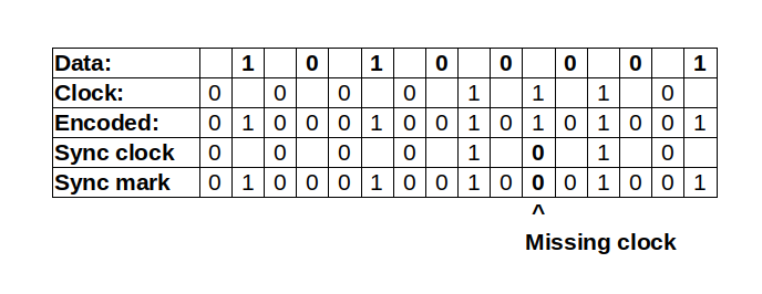
This missing clock bit was detected by the MFM controller and used to start a sector. This could be done for example by a comparator with this fixed bit stream pattern.
In [seib] and [ZaksBasic] you see more information on how the sync mark (missing clock bits) are used to determine start of a sector in MFM.
GCR (Commodore)
Commodore used a similar approach. The Commodore GCR encoding defined that no more than eight 1-bits should appear in a row on the media. Thus Commodore could use ten (or more) 1-bits on the media as sync mark. They only had to compare the bit stream from the media with a simple AND-gate (with the appropriate number of inputs), and make sure that the first data to be read started with a zero in GCR encoding to end the sync mark. This is ensured by using the value of “0x07” resp. “0x08” for data and header block marker. Both start with the nibble 0x0, that is encoded to 01010, which of course starts with a zero, breaking the sync mark.
GCR (Apple)
The original Apple II used FM encoding. As described in [diskii], the Disk II did not use any specific sync hardware. Instead it relies on specific data pattern that are self-synchronizing:
The shift register only starts shifting on the first 1-bit it encounters (remember, the first bit of an encoded byte must always start with 1). So if the data stream of your previous byte ends before a 0-bit, the next bit is delayed by the duration of the 0-bit. If that 0-bit is within a GCR data byte, the shift register is not delayed. This way, by placing 0-bits at the appropriate places you can synchronize the shift register even if the read started at different places. I can’t state it better than [diskii]:
Representing the resulting bit pattern as “1111111101111111101111111101111111101111111101111111101111111101111111101101010110101010”, close examination will show that if you follow the Woz machine's rule of skipping to a 1-bit and then collecting the next eight, then regardless of which of the first nine you begin on, you will always be reading the data stream with proper bit-cell and disk nybble framing before you hit the $D5 $AA pattern at the end.
For the 6-and-2 encoding, the synchronization pattern could also be shortend, but worked in the very same way.
From Physics to Data
MFM
The data in an FM or MFM data stream is interleaved with clock bits. Separating out the data from the clock bits seems to be an interestingly complex task. If you look at [datasep] you can see that this involves PLLs (phase-locked-loop oscillators) locking into the clock read from the data.
I will not go further into this here.
GCR (Commodore)
The Commodore disk drives are actually quite simple. The best way to understand is probably the 2031 technical manual [CBM2031], as it contains, for every page of schematics, a “theory of operation”. Especially the “high profile” version in the first half of the document is very easily readable.
The Commodore 2031 does not convert the actual data to GCR in hardware (as the older, dual drives by Commodore do, using a lookup-table in a ROM integrated in the GCR data path), so the CPU reads or writes the GCR data directly.
When a data byte needs to be written to the disk, an 8-bit shift register is loaded with the GCR data, and shifted out at the appropriate speed. Every one-bit is converted to a pulse by AND-ing it with a clock. The signal is then used to flip a simple flip-flop (74LS74 with the inverted output fed back to the input), whose outputs directly drive the read/write coils.
Reading is a bit more complicated. On the analog side, the signal from the read/write head is amplified, a low pass filter is applied, amplified again, and peak detected. A high pulse marks every magnetization change read. Pulses coming too quickly are filtered, and the pulse is given a defined length before it is sent to the digital board. If you look at the application note [AN917] by Motorola, you can see that this basically duplicates the schematics given there to read or write to a floppy disk.
On the digital board, every such read pulse triggers a new read sequence: the counter that produces a 1 MHz signal from the 16 MHZ clock is reset, the 1 MHz signal is further divided, this counter is also reset. Dividing the 1 MHz signal by four gives the 250 kHz bit frequency for double density media, creating a 4µs bit cell. After 2µs a 1-bit is clocked into the input shift register (to record the transition for the 1-bit). If, during the next 4µs after that, a magnetization change happens, the whole procedure starts again (especially resetting all the clocks). If not, a 0-bit of GCR data is recorded. Similarly for the next 4µs. After two 0-bits, however, a 1-bit is required by GCR to start the process again. The following diagram shows the timing.
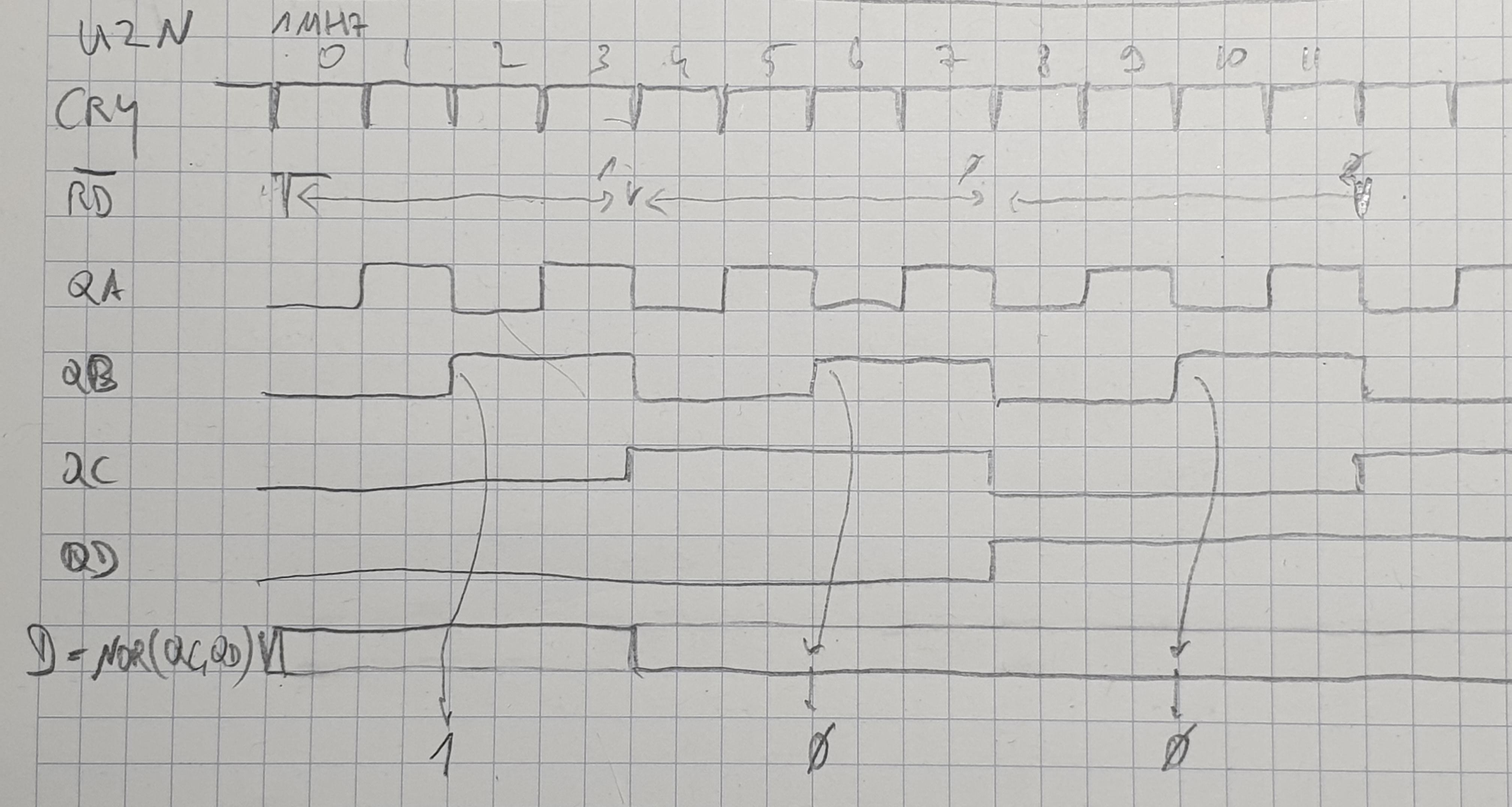
QA-QD are the outputs of a counter clocked with the 1MHz derived clock (CRY). Here QA is clocking with ½ MHz, i.e. 2µs cycle time, QB with ¼ MHz or 250 kHz, i.e. 4µs cycle time.
Note that this process still works even if the 1-bit after two 0-bits is off by almost 2µs plus or minus, i.e. a variance in the speed of the bits coming in of 2/12 = ⅙ = 16% is allowed. It is also self-synchronizing, as each 1-bit resets both the clock to generate the CRY (output of U5M) 1 MHz clock as well as the U2N counter whose outputs are shown here.
When the shift register is full, the CPU is notified by that fact by pulling the S.O. input of the CPU. This is a direct input to set the processor’s Overflow bit in the status register. Thus the processor can do an infinite loop like the following to read the data from the drive:
	waitdata	BVC waitdata
			LDA data
This is an important optimization, as a GCR byte contains 8 bits at a speed of 250kbit/second, i.e. in 4µs cells. Reading a full GCR byte only allows for 8 * 4µs = 32µs, i.e. 32 cycles for the 1 MHz 6502 CPU it used (technically a 6504, a 6502 with reduced address space).
GCR (Apple)
The GCR implementation for the Apple II on the analog side is similar to other implementations. In fact it used a Motorola 3470 Read Amplifier circuit. This integrated the read circuit which is still implemented with standard passive and op-amps for example on the Commodore disk.
The digital side of the Apple disk controller however, is much more complicated. It revolves around a state machine implemented with a 256 byte PROM controlling the shift register used to read data. You can find a deeper description in [diskii].
It is important to know that Wozniak started from the FM encoding scheme, and started storing four bits in each encoded byte. That also resulted in relying in the first bit being a 1 - the FM clock bit - so the processor could do a loop like this ro read the data:
    	waitdata    	LDA data
            		BPL waitdata
Later Wozniak found out that a more dense encoding allowed to store five bits in the abovementioned 5-and-3 encoding with the same hardware - also relying on the topmost bit set.
Later again, in 1980, the encoding was further changed to allow for two consecutive 0-bits, resulting in the 6-and-2 encoding. Here also the topmost bit was set in each encoded GCR byte.
From Data to Structure
Above I have discussed only the very basic physical format, and how to read and write the data. Of course this is only half the story. Using data encoding and sync marks, a track on the media can be divided into sectors that contain the data. Every sector has two parts - a header that is looked for when a sector is to be overwritten, and the actual data.
See [CBMformat] for an example.
There are many different types of formats for each of the different formats. Probably everyone (my age I guess) knows about the different PC type floppy disk formats. There are many different Apple DOS formats as well, including a fast loader format with sectors of 768 byte… For Commodore there are also different formats, but not as much as the others. Mostly they were used by fast loaders or copy protection. See [formats] for an overview.
Anyway, this maybe the topic for another article.
Did Commodore cheat?
Commodore released the floppy disk drives 8050, 8250 and 1001 where they were able to cram 500 kByte of data onto a single side of a Double Density disk. How is this actually possible?
First of all, Commodore used 100tpi Micropolis drives that provided 77 tracks instead of the previous 35 tracks of the older drives. But that should only get them from 170 kByte to about 340 kByte. Where does the rest come from?
Commodore is again using zoned bit recording, with four zones of different recording speeds:
| Tracks | Number of tracks | Number of sectors | Total kB for zone |
|---|---|---|---|
| 1-39 | 39 | 29 | 282.75 |
| 40-53 | 14 | 27 | 94.5 |
| 54-64 | 11 | 25 | 68.75 |
| 65-77 | 13 | 23 | 74.75 |
| 520.75 | |||
Each sector has 256 bytes as on the 170k formats. The number of sectors has increased, though, from 17 sectors on the innermost track to 23. The rotational speed is still 300 rpm - so what has happened?
Looking at the schematics one can see that the clock frequency for sending out the data bits has increased from 250kHz to 375kHz! There is some additional logic when comparing the login from the predecessor 3040 drive [3040logic] with the 8050 drive logic [8050logic] but that only seems to “shape” the outgoing pulse with delayed clocks. This looks to me as if there is some pre-compensation at work here. Which may be justified giving the higher frequency.
But, if there is a higher frequency, what about the bpi limits?
When we take 375kbit/s, and compute the number of bits written during a track of 200ms, we get 75kbit for a track. With 1.542 inches radius in the innermost track (guesstimated for 77 tracks with 100 instead of 96 tpi from the outer edge) we get 9.69in circumference and thus 7740bpi - well over the limit of 5900 bpi given for the actual media.
So why do these drives actually work?
References
- [density] Wikipedia on Disk density
- [history] Wikipedia on History of the floppy disk
- [perpend] Wikipedia on Perpendicular recording
- [oper] Wikipedia on Floppy disk operation
- [CBM] 8250/1001LP Disk drive technical manual
- [herb] http://www.retrotechnology.com/herbs_stuff/drive.html
- [CBMGCR] Wikipedia on GCR for Commodore
- [RLL] Wikipedia on RLL
- [MFM] Wikipedia on MFM
- [Heathkit] http://koyado.com/Heathkit/Z67-IDE_files/67Man-P2.pdf
- [seib] http://www.hermannseib.com/documents/floppy.pdf
- [ZaksBasic] http://bitsavers.trailing-edge.com/pdf/shugart/_appNotes/Lesea_Floppy_May78.pdf
- [CBM2031] Commodore 2031 disk drive service manual With the r/w logic here 2031/page-11r And the analog board here 2031/page-14r
- [a2dos] Apple II DOS Manual
- [AN917] https://archive.org/details/bitsavers_motorolaapndWritingInFloppyDiskSystems_1029819/page/n15
- [diskii] Explanation of the Apple Disk-II disk interface
- [datasep] Application Note for floppy disk data separators
- [formats] Wikipedia on floppy disk formats
- [CBMformat] Overview on sector structure on Commodore disks, Page 62/63 (page 70/71 of the PDF)
- [4040logic] Schematics for read/write logic of the Commodore 4040 disk drives
- [8050logic] Schematics for read/write logic of the Commodore 8050 disk drives
- [magnetic] Background material for magnetic recording materials from http://www.birmingham.ac.uk/research/activity/metallurgy-materials/magnets/Magnetic-Materials-Background-Information.aspx
- [magrec] Information on magnetic recording (from http://www.lintech.org/comp-per/ )